Braking Handlebar for Bicycle US Pub 2012/0240713

Today’s patent application attempts to solve the following problem:  deteriorated braking effect which may be caused by the braking cable becoming excessively bent.  In addition, the application presents a braking handlebar which is “easy to loosen or tighten.”

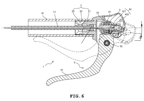
As illustrated in FIGS. 2 and 4, the braking handlebar includes a pressing section 31 (e.g., a lever), a pivoting section 32 (e.g., an axis for the lever to pivot), and an accommodating section 33 (e.g., a housing).  The accommodating section 33 is aligned with the handle 10 and carries a screw adjusting element 4.  The screw adjusting element 4 includes a cylindrical body 40 which carries an adjustable screw 41 and an inner screw tube 42.  A braking cable 11 extends through the handle 10 and the accommodating section 33 – including within the inner screw tube 42 and the adjusting screw 41.

FIG. 6 illustrates that when the pressing section 31 is not depressed, the core of the inner screw tube 42 is aligned with the handle 10 and that when the pressing section is depressed (braking), the core of the inner screw tube 42 is slightly lower than the core of the handle 10, being bent at an angle alpha.  This purportedly prevents an overly bent angle in the brake cable and reduces cable friction during braking.  An overall view of FIG. 6 and an enlarged view are shown below.

FIG. 6 Enlarged View

The application also asserts that the adjustable screw 41 within the screw adjusting element 4 allows the brake cable 11 to be “easily” tightened or loosened (See also FIG. 4 above).

Today’s patent application (U.S. Pub. 2012/0240713) was published on September 27, 2012. The full text may be found here (last visited October 3, 2012).  The inventor Szu-Fang Tsai of Changhua, Taiwan appears to have assigned the rights to Tektro Technology, Corp.

As of today’s date, the USPTO has filed a Non-Final Office Action dated October 2, 2012 asserting at least the following rejections:

  • 35 USC 112, second paragraph for failing to particularly point out and distinctly claim the subject matter; and
  • 102(b) as being anticipated by Wang (US Pat. 6,161,448).

I write this blog without taking a position as to the usefulness, desirability, novelty, aesthetics, functionality, etc. of the products or processes discussed in my posts.  Naturally, readers are free to take any position they prefer and comment accordingly, provided it is in good taste.  However, if I am silent with respect to your comment, such silence should not be construed as any agreement or disagreement to the comment; I hope you can appreciate that I simply prefer to remain neutral in such matters and merely report Patent Office and triathlon-related news.  Thanks!  🙂

Posted in Braking, Cycle, Cycling, Cycling Components | Tagged , , , , , , , , , , , , , , , , , | Leave a comment

Swim Cap with a Pocket

I like to swim at a place known to the locals here as Belle Isle Park.  Belle Isle is approximately a 1.5 mi.² island located in the Detroit River.  Generally, the most immediate reaction I receive when I tell people this is “ewww” or “gross”!

However, it turns out that due to its location, the water surrounding Belle Isle has been tested among the cleanest in the State of Michigan (Belle Isle is upriver of Detroit’s manufacturing and is fed by Lake St. Clair which in turn is fed by Lake Huron). In its heyday, Belle Isle was a gem of Detroit (and in many ways still is or at least could be); however, today it needs much TLC. In addition, it may not always be the safest place to hang out.

So when you go for a swim a Belle Isle, where do you put your keys? As a training triathlete, this is by far not the most embarassing thing I’ve done for my sport – I typically begin by removing my ignition key from the key ring (a key having electronics embedded therein), placing it in a Ziploc sandwich bag, expelling all the air that I can from the bag, sealing the bag, and then stuffing it up the leg of my swimming jammers.  Then, I walk down to the beach with what appears to be a cancerous growth on my quadricep.  Of course the entire time that I’m swimming, I’m periodically checking my leg to make sure this priceless package doesn’t slip away into the depths of the fast moving river – leaving me to begin the 15 mile walk home.

Of course, it’s not always keys we try to store on our person.  I know of at least one triathlete in the club to which I belong (shameless plug) who has attempted to place his not-so-waterproof GPS device within his swim cap as a means of attempting to track his distance during the swim.  The idea was two-fold:  first, collect data (something we triathletes are constantly starved for – although I question how often we purposefully USE the data); and second, to keep the GPS device from becoming water-logged.  Of course while this is no longer an issue for owners of the Garman 910XT (which is both waterproof and tracks distance when worn on the wrist), not everyone can afford the 910 XT!

Today’s simple invention may have helped my friend; it provides a pocket in a swim cap for holding an object.  As a matter of fact, the inventor specifically had in mind accomplishing the same thing as my triathlete friend – having a place to hold a GPS watch. According to FIG. 3, one embodiment of the swim cap has a zipper closure (9) which would run perpendicular to the base of the skull when the cap is worn.  The inventor does not limit the swim cap pocket to having zippers but also zip-locks, slide fasteners, Velcro, snaps, and buttons. The inventor also suggests a cord or tether like device at the pocket to secure the GPS watch or other electronic devices (e.g., an MP3 player) for extra loss-protection during the swim. The inventor further suggests that the material of the pocket is thin enough so that the GPS watch buttons may be depressed through the material (e.g., start and stop).

Today’s patent application (U.S. Pub. 2012/0131717) was published on May 31, 2012. The full text may be found here (last visited June 19, 2012).  The patent application appears to be owned by the inventor Bruce Richard Kaliner of Rye Brook, New York.

I write this blog without taking a position as to the usefulness, desirability, novelty, aesthetics, functionality, etc. of the products or processes discussed in my posts.  Naturally, readers are free to take any position they prefer and comment accordingly, provided it is in good taste.  However, if I am silent with respect to your comment, such silence should not be construed as any agreement or disagreement to the comment; I hope you can appreciate that I simply prefer to remain neutral in such matters and merely report Patent Office and triathlon-related news.  Thanks!  🙂

Posted in Equipment, Racing, Swimming, Training, Triathlon | Tagged , , , , , , , , , , , , | 1 Comment

UHF Timing System

How many times have you run a race and given any thought to all the effort that must go into timing your race (and everyone else’s)?

According to today’s patent, the previous systems required a time-consuming association process – i.e., associating each bib number with an identification (ID) number of a radio frequency identification (RFID) in the bib or chip.

For example, the patent states that previous chips were read-only memory (ROM) based RFID tags or chips which operate in the LF or low frequency (e.g., <135 kHz) or HF or high frequency (e.g., 13.56 MHz) bands.  Each ROM chip would have an associated identifier (e.g., a serial number).  The ROM chips would have be arranged on a wire or line in order to maintain their sequence.  And one at a time, each identifier would be then associated with a bib  number for the event.  Of course, the bib  numbers would also have be later associated with the identity of the participant too.  All this information would be kept in a spreadsheet or lookup table or other suitable database, and all the chips would have to be kept in the proper order.  Problems might arise when a human error was made in this association process; after which considerable efforts must then be made (e.g., by event organizers and managers) to reprocess the tags and bib numbers – essentially repeating the entire association process.

Generally, RFID tags operate by a reader (e.g., at the start and finish lines) emitting radio frequency (RF) energy in a region proximate to the chip or the bib (having a chip).  This energy is absorbed by the chip or tag and provided the amount of energy is sufficient, a current is induced in a coil in the tag which in turn activates an integrated circuit (IC) which transmits the tag’s identification back to the reader (e.g., at the start and finish lines).

US Patent 8,179,233 teaches that Class 1 Gen 2 tags require ultra high frequencies (UHF) and include writable memory into which data can be wirelessly encoded (rather than ROM memory).  Writable memory eliminates the more lengthy process of association – instead, the bib number can be written directly into the tag as its unique identifier.

The UHF range is approximately 900 MHz – 928 MHz.  The patent states that in the past, UHF was thought to be unreliable in applications such a race bib numbers, because too much radio frequency (RF) energy would be absorbed by the human body.  However, according to the patent, the inventor discovered that any absorption losses could be minimized by separating the tag from the human body by at least one inch or providing proper shielding.  The inventor further went on to prove that UHF was feasible using empirical data.

The inventor studied and tested various configurations of antennas and tags and conducted pilot testing in actual races – pilot locations included the Chicago and Detroit Marathons of 2007 where the primary timing chip was the ChampionChip and his chip was the pilot chip.

Today’s patent (U.S. Pat. 8,179,233) was issued on May 15, 2012. The full text may be found here (last visited May 23, 2012).  The patent appears to be owned by the inventor Arash Kia of Portland, OR.

I write this blog without taking a position as to the usefulness, desirability, novelty, aesthetics, functionality, etc. of the products or processes discussed in my posts.  Naturally, readers are free to take any position they prefer and comment accordingly, provided it is in good taste.  However, if I am silent with respect to your comment, such silence should not be construed as any agreement or disagreement to the comment; I hope you can appreciate that I simply prefer to remain neutral in such matters and merely report Patent Office and triathlon-related news.  Thanks!  🙂

Posted in Cycling, Racing, Racing, Racing, Running, Triathlon | Tagged , , , , , , , , , , , , , , , , , , , | Leave a comment

Adjustable Length Bicycle Stem

Nearly four years ago I started training for my first triathlon. I rushed out and found the best deal on a road bike but I could find. Why a road bike? Yes of course, because I couldn’t afford a triathlon bike at the time. While I’m ashamed to admit this fact, I’m sure I’m not entirely alone. In my haste, I rode a number of bikes and still managed to select one with frame that was too large for my build. This became readily apparent when I was first fit (or at least fit as good as possible) to that bike.

According to my fitter, a good fitting for that road bike required some adjustments to the stem.  As you may be aware, adjustability in the stem area is a one-way in which a bike fitter can better optimize the stack and reach to your body.

Today’s article pertains to a recently issued patent for an adjustable stem.

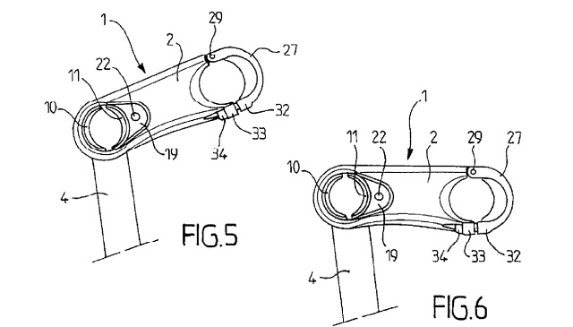
It is not uncommon to purchase a stem for your bike based upon a number of specifications including weight, length, and rise.  The ‘rise’ is the angular measurement between the stem and the head tube (more specifically, the absolute value of 90 degrees minus the total angle between the stem and head tube).  Thus for example, a stem with a 6 degree rise may be installed with a 96 degree angle between the stem and head tube OR, if it is inverted, with an 84 degree angle between the stem/head tube.

The invention provides a single stem with a variable rise.  The stem body 2 below is shown nearly perpendicular (or 0 degree rise) with respect to the head tube or steering tube 6 in FIG. 1.

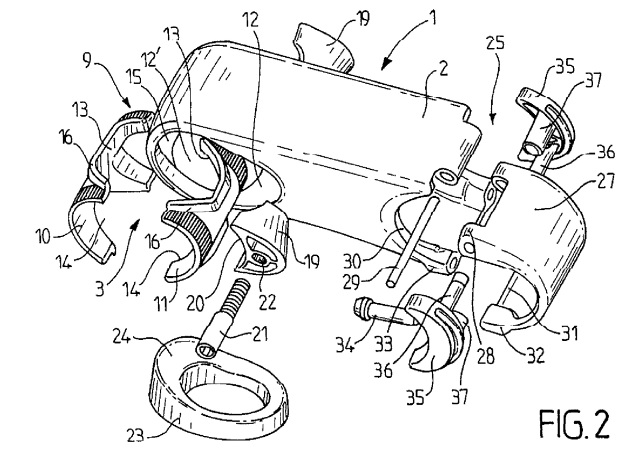
Below, FIG. 2 illustrates a means for tightening 9 the stem 2 to a pivoting tube 4 (which is the tube which rotates within the steering tube 6).  The tightening means 9 uses a wedge 19 which is secured by a tightening screw 21.  And this tightening means 9 may be adjusted to various rises or angles.

In addition, FIG. 2 illustrates a U-shaped cap 27 rotatable about axis 29 for securing the handlebars 26 using a pair of spacers 35.  The U-shaped cap 27 is at least partially intended to simplify adjustment.

FIGS. 5 and 6 illustrate the adjustability of the stem to achieve variations in the rise.

The patent includes another embodiment (FIG. 9) where the spacer 35 extends the entire width of the stem body 2 and connecting means (see 33, 34) are in a different arrangement.  It appears that this particular embodiment may be commercially available and is titled the “C-Stem”.

Today’s patent (U.S. Pat. 8,177,249) was issued on May 15, 2012. The full text may be found here (last visited May 23, 2012).  The patent is owned by Look Cycle International (Nevers, France).

The Legal Disclaimer:  I write this blog without taking a position as to the usefulness, desirability, novelty, aesthetics, functionality, etc. of the products or processes discussed in my posts. Naturally, readers are free to take any position they prefer and comment accordingly, provided it is in good taste. However, if I am silent with respect to your comment, such silence should not be construed as any agreement or disagreement to the comment; I hope you can appreciate that I simply prefer to remain neutral in such matters and merely report Patent Office & triathlon-related news. Thanks! 🙂

Posted in Cycle, Cycling, Cycling Components, Fitting | Tagged , , , , , , , , , , , | Leave a comment

Sports Bra

Ok, before I begin to venture down this road, I want to profess to the ladies reading this, I don’t know much about sports bras and I’m not pretending to!  If you have a comment on today’s post (and I’ve just simply missed the boat), feel free to really lay it out there; but please be kind!

That being said, I do have a very athletic spouse with whom I’ve gone shopping on numerous occasions for women’s athletic apparel.  Allow me to say:  I don’t envy you gals!  Finding the right fit appears to be tiresomely difficult.

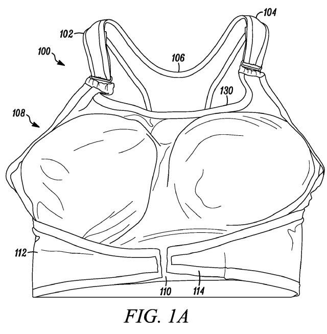
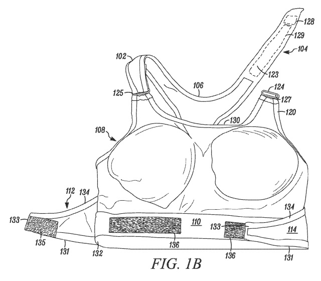
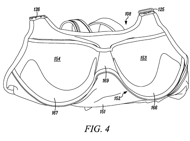
Today’s topic pertains to an exercise or sports bra that appears to alleviate some fitting concerns.  The garment may include adjustable shoulder straps (102, 104) and under supports (166, 167) with gel padding.  In addition, the garment may be produced using commercially available fabrics that breathe and wick moisture away from the body.

Unique to this garment is a circumferential tightening structure which allows adjustment around the woman’s torso.  Each side of the garment has a rear and front panel (106, 108).  And each side may have a flap (112, 114) that extends (for example) from the rear panel (106) to the front panel (108).  The flap may be fixed at the rear panel but be attachable and adjustable to the front panel.  And the attachable portion may be hook and loop (135, 136) (e.g., Velcro (TM)).

Thus, the circumferential tightening structure may provide a more customized fit and additionally may make the garment universally appealing.

Today’s patent was issued on May 8, 2012 to Jennifer V. Swendseid of St. Louis Park, MN. The full text may be found here.  The patent is assigned to Heart & Core, LLC, also in Minnesota. (both sites were last visited May 9, 2012)


I write this blog without taking a position as to the usefulness, desirability, novelty, aesthetics, functionality, etc. of the products or processes discussed in my posts.  Naturally, readers are free to take any position they prefer and comment accordingly, provided it is in good taste.  However, if I am silent with respect to your comment, such silence should not be construed as any agreement or disagreement to the comment; I hope you can appreciate that I simply prefer to remain neutral in such matters and merely report Patent Office news.  Thanks!  🙂

Posted in Athletic Apparel, Running, Women's | Tagged , , , , , , , , , , | 2 Comments

Jogging Stroller Math?

Sometimes, getting in those running miles equates to babies going for a ride!

So, need a stroller?  Come to my house and do your shopping.  During regular business hours my wife and I will allow you to take a test drive of some of the latest stroller technology.  In raising a toddler son and recently adding a baby girl, it seems that the quantities of strollers around our house has also doubled.

First there was the family stroller – built like a tank – it accommodates an infant carrier and has the storage space of a small flatbed pickup.  Then, of course, the running stroller.  And don’t forget the umbrella stroller.  But when baby girl came along, suddenly the stroller count doubled!

I’m hoping my wife doesn’t read today’s post – a walking or running stroller with a bit of a twist.  The stroller shown below aims to “accommodate the user’s natural and synchronous arm motion while simultaneously distributing between both of the jogger’s arms the force required to propel the stroller.”

The stroller has two arm members (21) which ultimately interact with the drive tubes (23, 52).  A coupling member may be positioned between the two tubes.  According to the patent, the term coupling member includes the following exemplary definition:  mechanism for facilitating natural limb movement and facilitates an even distribution of force between the user’s arms as required to propel the stroller.  For example, the coupling member may include a bevel gear on the end of each drive tube, plus a center bevel gear (37) connecting the two.  When the user’s arms apply substantially equal forces on each arm member, each drive tube applies a rotational force to the rear wheels.  Thus, as the user runs (for example) the natural pendulum action of the user’s arms is used to drive the arm members and thus propel the stroller.

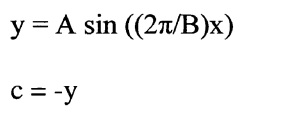
The engineers, mathematicians, and scientifically inclined may find it of interest that one of the patent’s independent claims includes the limitation that the coupling member may be defined with the mathematical equations:

The ‘y’ term equals the position of the user’s left arm.  Thus, c or -y equals the position of the user’s right arm.  The other variables include:

  • A = amplitude, and half the distance between the arm’s maximum forward position and maximum back position
  • B = period, and represents the time to complete one cycle of arm movement
  • x = time

Remember when you sat in algebra and asked the question that most every student eventually asks:  “When am I ever going to use this stuff?”  Well . . .

So, the claim in part states:  . . .  a coupling member mechanically coupled to the first arm member and to the second arm member such that the position of the first arm member relative to the position of the second arm member can be defined with the mathematical equations:

y=A sin ((2*pi/B)x)

c=-y

wherein, in one complete cycle of arm movement during the act of pushing the stroller . . .

So adding JOGGING + STROLLER + MATH must equal  >>

Well, there you have it.  Today’s patent was issued on May 8, 2012. The full text may be found here (last visited May 9, 2012).  The patent appears to be owned by its inventor, Michael J. Dresher of Wichita, KS.


I write this blog without taking a position as to the usefulness, desirability, novelty, aesthetics, functionality, etc. of the products or processes discussed in my posts.  Naturally, readers are free to take any position they prefer and comment accordingly, provided it is in good taste.  However, if I am silent with respect to your comment, such silence should not be construed as any agreement or disagreement to the comment; I hope you can appreciate that I simply prefer to remain neutral in such matters and merely report Patent Office news.  Thanks!  🙂

Posted in Running, Strollers | Tagged , , , , , , | 1 Comment

Tour de Trainer? Tourmalet Anyone?

We had glimpses of Spring here in Michigan in March this year – HIGHLY unusual!  I removed the bike from the trainer for the first time in months.  I took the time to remove the old tire which was virtually glued to my trainer’s resistance cylinder (i.e., that part where the rubber meets the faux-road) and replaced it with that good rear road tire I’d been saving since last Fall.  However, the 70 degree weather we had was short lived and before I knew it, I was back on the trainer.

Please don’t get me wrong, I believe riding the trainer is worthwhile – and is certainly better than not riding at all.  However, those of you who ride it for weeks on end know . . . it’s just not the same!

Today’s invention attempts to change all that – by better simulating outdoor riding by incorporating simulated ascents and descents with changing resistance to your favorite cycle.

And for those of you who are familiar with Tourmalet, that was merely a tease (although this invention may have potential); for those who may not be familiar, click here.

According to the disclosure, accomplishing realistic ascents and descents cannot be achieved by simply lifting and lowering the front wheel (automated or otherwise).  This is because as the front wheel is elevated, the rear wheel departs or moves laterally away from the resistance cylinder.  This lateral departure can be contributed to the fact that the front tire is merely being elevated – not rotated about a pivot point centered on the rear axle.  (In Physics terms, there’s X- and Y-components involved.)  Naturally, as the rear wheel laterally departs from the resistance cylinder, resistance decreases rather than increases.  And if we’re attempting to simulate an outdoor climb, we obviously do not want our resistance decreasing as we go uphill – however awesome that might sound to those with Superman-syndrome!

The disclosure reveals various ways to overcome this lateral departure and for the sake of brevity, I will only illustrate and describe one embodiment here.  A portion of FIG. 1A above is enlarged below.

This figure illustrates the rear tire (26) pressing against a resistance cylinder (30) due to a constant pressure spring (40).  A U-bar (48) is coupled to the vertical bar (35) of the trainer by a retraction spring (41).  The open ends of the U-bar are coupled to the axle on both sides of the rear wheel.  Thus, spring (41) draws the bike rearward while the spring (40) applies pressure against the rear tire to achieve resistance.

The rear axle of the bike is supported by two rollers (45) which are supported by two transition platforms (50).  So when the front wheel is elevated, the rear wheel translates rearwardly because the spring (41) is pulling upon the rear axle and the axle is free to move due rollers (45) rolling on the platforms (50).

Now taking a look at the front of the bike – a lifting mechanism (15) elevates and lowers the front wheel.  The mechanism has a front platform (19) atop a height controller (18).  One interesting embodiment of the controller (18) includes a CD player for playing computerized course profiles (e.g., real world courses).  Tourmalet anyone?  {On a personal note: for those of us in lower Michigan training for IM Mont Tremblant – this sort of device is capable of providing us the hills to train upon that just are not otherwise available here!}

As I previously stated, the patent contains numerous other embodiments – having various resistance-applying mechanisms, having various means to support the cycle, etc.  I invite you to take a look for yourself!

This invention was granted a U.S. patent on April 24, 2012 and may be found here.  Additional images may be found here.  (last visited May 2, 2012)

Happy ‘hilly’ Training!


I write this blog without taking a position as to the usefulness, desirability, novelty, aesthetics, functionality, etc. of the products or processes discussed in my posts.  Naturally, readers are free to take any position they prefer and comment accordingly, provided it is in good taste.  However, if I am silent with respect to your comment, such silence should not be construed as any agreement or disagreement to the comment; I hope you can appreciate that I simply prefer to remain neutral in such matters and merely report Patent Office news.  Thanks!  🙂

Posted in Cycling, Trainer, Training | Tagged , , , , , , , , , | Leave a comment

Illuminated Helmet with Programmable Lamps and Proximity Sensor

The lucky few do triathlon as their livelihood.  I am not one of those lucky few!  And more likely than not, you aren’t either!

If this is true, inevitably you find yourself riding at the crack of dawn or getting caught too far away from the car as the sun goes down – all for the sake of getting those few extra miles in while juggling day-to-day responsibilities.

Today’s invention provides another way for you to be seen by vehicle drivers when visibility is low, as you try to get in those extra miles.  The invention includes at least two implementations using multiple LEDs (or light-emitting diodes) to alert drivers to your presence.

The first implementation has multiple LEDs within the recesses (106) of the helmet in the “impact area(s)” (or the primary area designed to absorb impact during a collision).  Of course, as styles of helmets vary, so also may the arrangement of LEDs.

The second implementation locates the LEDs in the “non-impact area” of the helmet (112).

In both implementations, the LEDs may light or flash in a conspicuous manner and the patent describes specific flashing patterns.

In addition, the helmet may include a proximity sensor which actuates the LEDs automatically when you place the helmet on your head.  For users who desire a tactile switch, a switch may also be provided that enables you to turn ON the LEDs while riding.  And you will know that the lights are ON because the helmet will beep or vibrate when the switch is flipped (i.e., you will not need to remove the helmet to determine whether the LEDs actually turned ON)!

This invention was granted a patent on April 17, 2012 and may be found here (last visited April 22, 2012).


I write this blog without taking a position as to the usefulness, desirability, novelty, aesthetics, functionality, etc. of the products or processes discussed in my posts.  Naturally, readers are free to take any position they prefer and comment accordingly, provided it is in good taste.  However, if I am silent with respect to your comment, such silence should not be construed as any agreement or disagreement to the comment; I hope you can appreciate that I simply prefer to remain neutral in such matters and merely report Patent Office news.  Thanks!  🙂

Posted in Cycling, Helmet, Training, Triathlon | Tagged , , , , , , , , , , , , , , | Leave a comment

Relief from Cycling Hot Spots

When I was newer to triathlon, I used to experience numbness and discomfort in my feet when I went for a bike ride for anything over a couple hours.  This numbness/discomfort always originated at the hot spot – the region on the bottom of the foot which is directly over the pedal cleat (using clipless cycling shoes).

As today’s patent application explains, “long or medium distance cycling exposes the foot to continuous pressure and vibration in the hot spot.”

The application goes on to remedy this issue by providing an innersole for a cycling shoe that has a gel or gel-like insert in the problem region 20 (FIG. 1).

This insert 20 may have multiple polymeric layers such as a polyurethane gel.  The application discloses examples of the thicknesses of the layers and their respective durometry (e.g., their hardness).  The figure below illustrates a cross-section of the insert in the insole showing these layers.  You may notice the grooves in the upper layer – according to the disclosure, these grooves may enhance vibrational dampening and improve air circulation.

This patent application was published on April 19, 2012. The full text may be found here (last visited April 21, 2012).

The application is assigned to G-Form.  It appears that at least one implementation of this technology is already being sold – bike shoe insole.


I write this blog without taking a position as to the usefulness, desirability, novelty, aesthetics, functionality, etc. of the products or processes discussed in my posts.  Naturally, readers are free to take any position they prefer and comment accordingly, provided it is in good taste.  However, if I am silent with respect to your comment, such silence should not be construed as any agreement or disagreement to the comment; I hope you can appreciate that I simply prefer to remain neutral in such matters and merely report Patent Office news.  Thanks!  🙂
Posted in Cycling, Discomfort, Shoes, Triathlon | Tagged , , , , , , , , , , | 2 Comments

Swim Paddles to Minimize Shoulder Strain

I had just finished my swim sets a couple days ago at the pool (doing freestyle) when the young man who was sharing my lane told me that he was training for his first triathlon.  Naturally, this spawned additional conversation.  Before we were finished, he told me how much he’d been swimming and asked: “Can you help me figure out why my shoulders are killing me?”

At some point in your triathlon training, you are likely to increase your swim volume.  In many cases, this increase in volume combined with defects in your form may lead to shoulder impingement and pain.  Furthermore, this strain may be exacerbated by the use of swim paddles.

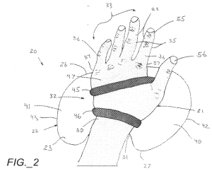
However, today’s invention implies that even if the swimmer’s form is good and healthy, the use of conventional swim paddles impairs that form and stresses the swimmer’s shoulder.  According to the disclosure, this stress occurs because conventional paddles act as an extension of the hand and require the swimmer to exert substantial pressure on the paddle with both the fingers and the palm of the hand – wherein the natural stroke disproportionately uses the palm.  Thus, the force applied by the extended fingers on the paddle impairs the swimmer’s technique.

The invention remedies this impediment by providing a new swim paddle that does not permit the swimmer to use extended finger pressure.  In fact, the swimmer may fold the fingers around the leading edge of the paddle and grip it.

Another feature of this invention includes a means to increase the overall weight of the swim paddle – presumably realized by the user when the arm is in the recovery phase of the freestyle stroke.  This weight is an additional pad of material which may be added to the primary plate shown above.  In one instance, this weight pad may include wool felt material which absorbs water to add weight.

This patent application published on April 19, 2012.  The full text may be found here:  (last visited April 21, 2012).

The application is assigned to Aquavolo.  According to the website, the “AquaVolo Team is an international group of competitive swimmers collaborating to create cutting-edge training gear for swimmers.”


I write this blog without taking a position as to the usefulness, desirability, novelty, aesthetics, functionality, etc. of the products or processes discussed in my posts.  Naturally, readers are free to take any position they prefer and comment accordingly, provided it is in good taste.  However, if I am silent with respect to your comment, such silence should not be construed as any agreement or disagreement to the comment; I hope you can appreciate that I simply prefer to remain neutral in such matters and merely report Patent Office news.  Thanks!  🙂

Posted in Equipment, Paddles, Swimming, Triathlon, Uncategorized | Tagged , , , , , , , , , , , , , , | 2 Comments